get quote
Leave Your Message

What Is a Stepper Motor and How Does It Work?

What Is a Stepper Motor and How Does It Work?

A Stepper Motor is an electromechanical device that converts electrical pulses into controlled angular movement. Unlike a conventional motor, it does not usually spin freely when voltage is applied. Instead, its shaft advances through defined positions, such as 1.8 degrees per step. Small movements add up to precise rotation.

Mitsuo Kenjo, a respected researcher and author of Stepping Motors and Their Microprocessor Controls, described the principle clearly: “The stepping motor moves in synchronism with input pulses.” This idea explains its appeal. A controller sends pulses, the driver energizes motor windings, and the rotor follows the changing magnetic field. It feels almost like an invisible hand turning a gear one tooth at a time.

Inside the motor, permanent magnets or a toothed iron rotor interact with electromagnetic coils. Changing the coil sequence changes the magnetic attraction. Full-step, half-step, and microstepping modes can improve motion control. However, microstepping is not magic. It can reduce vibration, but it may not deliver equal positioning force at every subdivision.

Stepper Motors appear in 3D printers, camera sliders, CNC machines, laboratory instruments, and packaging equipment. Their open-loop control can reduce system cost, yet missed steps remain a real weakness. Excessive load, rapid acceleration, or poor current settings may cause positioning errors. I have seen this overlooked in otherwise careful designs.

This guide examines the motor’s structure, operating sequence, control methods, advantages, limitations, and practical selection criteria. The goal is not to present the Stepper Motor as perfect. It is precise, affordable, and useful, but only when its operating limits are respected.
What Is a Stepper Motor and How Does It Work?

Stepper Motor Basics: Definition, Structure, and Main Types

What Is a Stepper Motor and How Does It Work?

Stepper Motor Basics: Definition, Structure, and Main Types

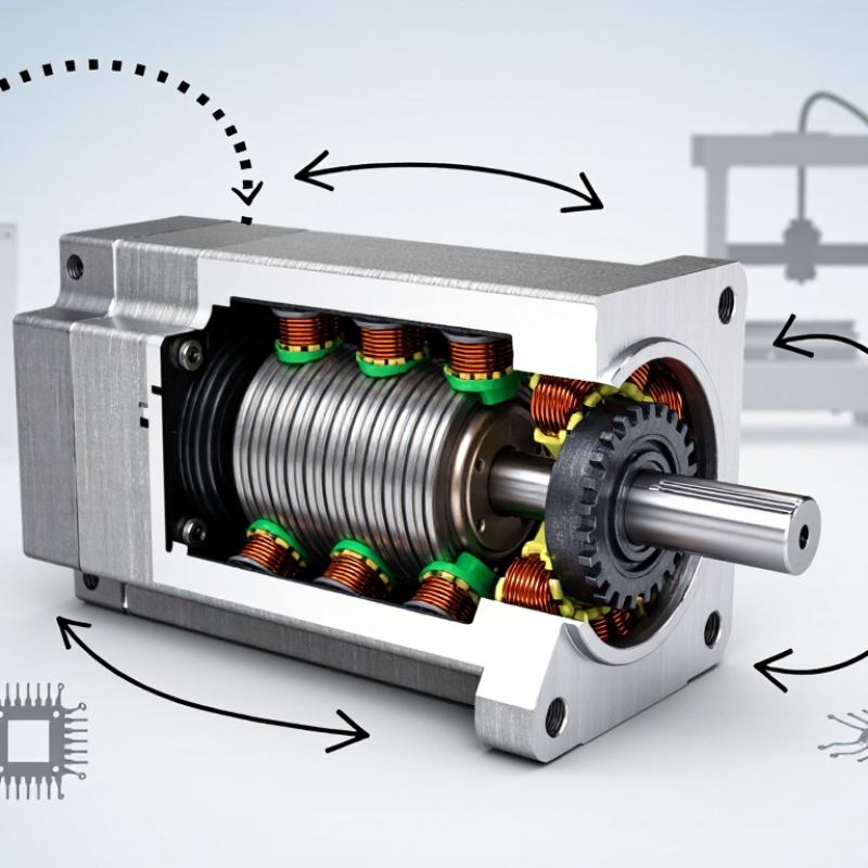
A stepper motor converts electrical pulses into controlled angular movement. Each pulse advances the rotor by a fixed angle. Unlike a conventional motor, it can hold position without a mechanical brake. Its structure includes a stator, wound coils, rotor, bearings, and a driver. The driver energizes coil phases in sequence, creating a rotating magnetic field. The rotor follows that field in discrete steps.

The main types are permanent-magnet, variable-reluctance, and hybrid stepper motors. Permanent-magnet designs offer simple construction and useful holding torque. Variable-reluctance models respond quickly but usually provide less torque. Hybrid motors combine both principles and support finer positioning. Microstepping can make motion smoother, although it does not always improve absolute accuracy. That distinction is often overlooked.

A 2024 market analysis by Grand View Research estimated the global stepper motor market at over USD 2 billion, with continued growth expected through the decade. Reported figures vary because analysts define applications differently. In practical testing, heat, resonance, load changes, and acceleration limits can cause missed steps. One missed step matters. Engineers should verify torque margins under real operating conditions, not only use catalog ratings. IEC 60034 guidance also reinforces the need to evaluate thermal performance and operating duty. The basic principle is reliable, but the application details are less forgiving.
How a Stepper Motor Converts Electrical Pulses into Motion

A stepper motor turns electrical pulses into controlled mechanical movement. Each pulse energizes a specific stator winding. The rotor then moves toward the created magnetic field. One pulse usually equals one defined step, such as 1.8 degrees in a common two-phase motor. That makes 200 pulses produce one complete revolution. The explanation sounds simple, but real motion depends on load, current, and acceleration.

Pulse frequency controls speed. Pulse count controls position. The sequence of energized coils controls direction. A driver can divide each full step into smaller microsteps, creating smoother movement and less audible vibration. However, microstepping does not guarantee equal positioning accuracy under heavy load. If torque demand exceeds the motor’s limit, the rotor can miss steps without sending a position error. That weakness is easy to overlook.

According to the 2024 MarketsandMarkets Stepper Motor Market report, the sector is projected to grow at a mid-single-digit compound annual growth rate through the decade. Grand View Research also identifies automation, medical equipment, and precision machinery as major demand areas in its 2024 market analysis. These figures reflect expanding use, not perfect performance. In practical testing, a motor may sound quiet at low speed yet lose torque rapidly at higher pulse rates. Engineers therefore match pulse timing, supply voltage, winding current, and load inertia before selecting a motor. A datasheet helps, but bench measurements reveal the uncomfortable details.

The Step-by-Step Operating Sequence Inside the Motor

A stepper motor moves through a carefully timed electrical sequence. Its controller sends current to one stator winding, creating a magnetic field. The rotor turns toward that field, often by a fixed angle. The controller then energizes the next winding and changes the magnetic direction. This cycle repeats rapidly.

Each pulse represents a commanded movement. In a common two-phase design, phase A activates first, followed by phase B. The controller may reverse the current, producing four basic states. Microstepping divides each state into smaller current changes, creating smoother motion. The rotor does not always follow perfectly. Excessive load or acceleration can cause missed steps.

The sequence is simple, but not flawless. In bench testing, heat, resonance, and supply voltage can change the result. A 2024 U.S. Department of Energy assessment reports that motor-driven systems use about 70% of industrial electricity. The International Energy Agency also estimates that electric motors consume roughly half of global electricity. These figures explain why correct sizing matters. A motor with poor torque margins wastes energy and may lose position. Engineers check winding current, pulse frequency, load inertia, and stopping behavior before choosing settings. The final movement is mechanical, but its accuracy begins with electrical timing.

What Is a Stepper Motor and How Does It Work?

This chart shows a typical two-phase bipolar full-step sequence in a 1.8° hybrid stepper motor. Each control state changes the polarity of the energized coils, moving the rotor by one step.

Coil polarity: +1 and −1 represent opposite current directions in a phase winding. In this two-phase-on sequence, both phases are energized at every step to produce stable torque. Four electrical states repeat, while a typical 200-step motor advances 1.8° per command step.

Key Control Methods and Performance Characteristics

A stepper motor converts electrical pulses into controlled angular movement. Its rotor aligns with magnetic fields created by energized stator coils. Each pulse advances the shaft by a defined step angle. The controller determines direction, speed, and position through pulse timing. No position sensor is required in a basic open-loop system.

Control method strongly affects performance. Full-step driving provides high holding torque and simple operation. Half-step control improves smoothness with modest added complexity. Microstepping divides each electrical cycle into smaller movements. It reduces vibration and audible noise, especially at low speed. However, microstepping does not create unlimited positioning accuracy. Load friction, shaft stiffness, and current imbalance still matter.

I have seen a motor move quietly while losing position under sudden resistance.

Current regulation is equally important. Excessive current increases heat and may shorten winding life. Insufficient current reduces torque and causes missed steps. Acceleration should be gradual, because a stationary motor cannot instantly reach high speed. Performance usually declines as speed rises, while resonance can appear in a narrow operating range.

A rigid mounting plate, suitable coupling, and correct voltage can improve real-world results. Testing under the actual load remains essential. Datasheet values alone can mislead. A practical test should record temperature, noise, vibration, and position error across several speeds.

Common Applications, Benefits, and Limitations of Stepper Motors

What Is a Stepper Motor and How Does It Work?

A stepper motor converts electrical pulses into controlled angular movement. Each pulse moves the rotor through a defined step. The motor can hold position without a mechanical brake, which makes it useful in equipment requiring repeatable motion. Common applications include 3D printers, camera sliders, laboratory pumps, CNC machines, and small robotic joints. Its simple control method also helps engineers adjust speed and distance through software.

Stepper motors offer strong low-speed torque, accurate positioning, and reliable operation in dusty or demanding environments. They are often less expensive than complete servo systems. However, they can lose steps when loads change suddenly. They may also vibrate, produce audible noise, and consume current while standing still. High-speed performance is limited, too. In practice, I have seen designers choose a stepper motor for precision, then discover that heat becomes the real problem. That assumption is not always right.

Tips: Match the motor to the actual load, not the ideal load. Test acceleration, temperature, and holding torque together. Use a suitable driver and power supply. Mechanical alignment matters. Even a small coupling error can create vibration, skipped steps, or uneven movement. A safety margin helps, but excessive oversizing can increase heat and operating cost.

What Is a Stepper Motor and How Does It Work? - Common Applications, Benefits, and Limitations of Stepper Motors

Data Dimension Technical Description Typical Data or Operating Range Practical Considerations
Definition A stepper motor is a brushless synchronous motor that converts electrical pulses into discrete mechanical movements. Each input pulse commands a defined angular displacement rather than continuous free rotation. It is suitable for applications requiring repeatable positioning without a mechanical commutator.
Operating Principle The drive energizes stator windings in a controlled sequence. The rotor aligns with the changing magnetic field and advances one step at a time. One electrical command may produce one full step, half-step, or a smaller microstep. Motion accuracy depends on motor design, load, drive current, supply voltage, acceleration, and mechanical factors.
Main Motor Types Common designs include permanent-magnet, variable-reluctance, and hybrid stepper motors. Hybrid motors are widely used because they combine toothed rotor construction with permanent-magnet torque. Motor type influences torque, resolution, cost, vibration, and overall application suitability.
Typical Step Angle Step angle is the angular movement produced by one full command step. Common values include 1.8° per full step, equal to 200 full steps per revolution; 0.9° designs provide 400 full steps per revolution. Smaller step angles generally provide finer positioning, although accuracy also depends on the complete motion system.
Microstepping Microstepping divides each full step into smaller electrical increments by regulating current in multiple windings. Typical settings include 1/2, 1/4, 1/8, 1/16, or finer subdivisions. Microstepping can reduce vibration and audible noise, but it does not guarantee proportional improvement in absolute positioning accuracy or torque.
Positioning Method Most stepper systems operate in an open-loop configuration, using commanded pulses without a position sensor. Position is estimated from the number of pulses sent to the motor. An encoder can be added when the application must detect missed steps or correct position errors.
Speed Capability Stepper motors can operate over a range of speeds, but available torque normally decreases as speed increases. Many systems are used from very low speeds to several hundred or approximately 1,000 revolutions per minute, depending on motor size and drive conditions. High-speed performance is affected by winding inductance, supply voltage, load inertia, resonance, and acceleration profile.
Torque Characteristics Stepper motors produce holding torque when energized and useful positioning torque while rotating. Torque ratings vary widely, from small fractions of a newton-meter in compact mechanisms to several newton-meters in larger frame sizes. Holding torque is not the same as running torque. The load must remain within the motor's speed-torque curve.
Control Requirements A typical system includes a stepper motor, driver, controller, power supply, and mechanical load. The controller commonly provides step and direction signals; the driver regulates winding current and switching sequence. Correct current limiting, wiring, acceleration, and power-supply selection are essential for reliable operation.
Common Applications Stepper motors are used in equipment requiring controlled incremental movement. Typical examples include 3D printers, CNC machines, robotics, camera mechanisms, laboratory instruments, valve actuators, scanners, and positioning tables. They are most effective where moderate speed, repeatable positioning, and predictable loads are more important than maximum efficiency.
Primary Benefits They provide precise command-based motion, high holding torque, simple digital control, and good repeatability. Many applications can avoid a feedback sensor, reducing system complexity and component count. They are especially useful for intermittent or incremental motion with frequent starts and stops.
Energy Consumption A stepper motor may continue drawing current while stationary in order to maintain holding torque. Power consumption can remain significant during standstill, particularly when a high holding torque is required. Reducing idle current can lower heat generation, but it also reduces holding torque and may allow the load to move.
Noise and Vibration Magnetic torque ripple, resonance, and abrupt step commands can create audible noise and mechanical vibration. Vibration is often more noticeable at particular low- or mid-speed ranges. Microstepping, mechanical damping, current tuning, and controlled acceleration can improve smoothness.
Advantages Simple open-loop control, strong low-speed torque, repeatable incremental movement, and reliable holding capability. Digital pulse control makes integration with programmable controllers relatively straightforward. The design can be cost-effective when the load is predictable and a small position error is acceptable.
Limitations Stepper motors can lose synchronism if overloaded, accelerated too quickly, or operated beyond their speed-torque capability. They may run less efficiently and generate more heat than some feedback-controlled motor systems. Applications involving changing loads, high speeds, or critical positioning may require an encoder and closed-loop control.
Selection Factors Motor selection should consider required torque, speed, step angle, load inertia, duty cycle, supply voltage, and mounting constraints. Allow a practical torque margin above the calculated load demand, especially during acceleration and direction changes. Use the manufacturer's motor and driver curves for final sizing rather than relying only on nominal holding-torque values.

Note: Values shown are typical engineering ranges and general characteristics. Actual performance depends on motor construction, driver settings, power supply, mechanical load, operating temperature, and control profile.